
The mechanical housing has been kept as rugged and straight forward as possible; a simple frame 425mm wide, 400mm high made out of inch square mild steel to be nice and sturdy and leave plenty of room for fitting things in.

The top, front and side panels are laser cut out of 6mm oak veneered MDF, stained in “Terra” which personally I think looks quite good. Depending on funding and opinion I will endeavour to offer a range of stains and possibly some other basic material such as anodised aluminium. Thoughts?


The rear and bottom panel are laser cut out of 3mm mild steel, since all the heavy stuff (motor, driver, PSU) will be mounted on the rear panel and the feet that will be supporting the entire display will be mounted on the bottom. This means that there will only be 3 “attractive” sides on the display, the rear will have a bloody great heatsink hanging out of it, along with the motor control panel and HDMI, power and USB cables.
If the Kickstarter gets funded then the finalised product will look lovely from all sides (kind of the point of having a spherical display, right?). The motor driver will be significantly smaller with no external heatsink required, no interactive motor control interface and no HDMI or USB cables. All that would remain would be a power cable which would either be a standard kettle C13 plug or a hard wired cable.
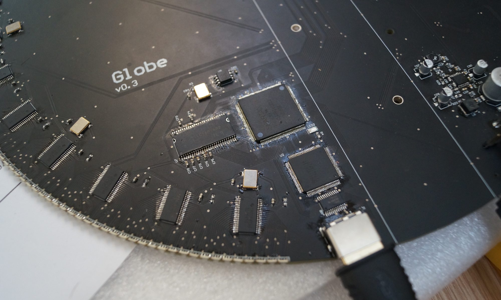
For simplicity and sturdiness a bearing holds the shaft at the bottom and top panels and the shaft extends about 250mm up the PCB. Therefore with a little bit of space between the bottom of the PCB (for cables to go in) and the housing we have a total length of ~720mm. The bearings and slip rings have a bore of 38.1mm so we have a 720mm long, 38.1mm diameter shaft, which needs a slot of ~290mm milling down from the top and a hole of 14 data and 4 power cables worth up from the bottom. Along with some other slots and holes that’s pretty much all there is to it. Unfortunately due to its size its a fairly pricey piece, even by buying in a 12.7mm thick walled tube to save on having to drill the central hole it’s still looking like a £250 job (and that’s getting it done in house).
Aside from a pair of pulleys, a drive belt and some mild steel right angle sections on the corners of the box keep things neat that pretty much sums up the lower section.
The upper section is comprised of the previously mentioned acrylic cube which should provide an attractive enough protective casing to curb any desires to see how much it hurts if you poke a finger in while it spins. It also means that if one of the components makes a bid for freedom it should be suitably contained. This is set within a square section of aluminium U channel with a rubber insert, a couple of grub screws providing a little bit of force to hold it…in case some of those who are REALLY determined to poke a finger in decided to remove the casing too.
If the Kickstarter goes ahead I will more than likely replace the acrylic with some form of toughened glass which would become a more viable option if produced in bulk. I would also bump up the safety a bit more, adding a sturdier locking mechanism and various sensors to make sure the device was being operated in a safe manner.